 Andrew Betts


The solution to my habitual inability to look after houseplants is probably to spend more time learning about plants and less time messing about with microcontrollers, but what if I could spend more time on microcontrollers AND also reduce the plant casualty rate at the same time?!
There are lots of indoor plant watering systems available on the likes of Amazon and AliExpress, but they are typically designed with a single outlet that delivers the same amount of water to all plants via one daisy-chained pipe. This is quite efficient but doesn’t really work if you have tiny succulents that require almost no water and a monsterous monstera that drinks litres of it daily.
Requirements and design trade offs
Let’s start with a list of requirements:
-
Every plant gets different amounts of water, on different intervals
Some commercial systems have adjustable ‘drip heads’ so you put a constant water flow in, and it comes out of different outlets on the pipe at different rates. That’s “OK” but unless you have a very clever pump that can detect backpressure I don’t see how you ensure that the amount of water being pumped into the pipe matches the total flow demands of all the nozzles - and it’s no good if you want some plants watered daily and others every couple of weeks. -
Reactive to how dry the plant is
Ideally we want not just to give each plant a personalised watering plan, but also to adjust it automatically based on how wet the plant is. -
Low per-plant complexity and cost
It’s not really viable to have a pump and microcontroller for every plant. And I really don’t want to be assigning IP addresses to my plants. -
No siphoning or leaking
My house is tall and thin, and the plants are spread over 4 floors in a narrow column. If I put a tank at the very top, there’s going to be a big siphon effect created by the weight of the water in the pipe leading down to the plants on the bottom floor. Pumps are not valves, and are usually not designed to prevent water flowing through them when the inlet is pressurised. -
Low chance of disaster
The typical build quality of my home-made projects is highly questionable, so we probably don’t want this thing to be connected to an endless water supply, you know, just in case. So let’s just say up front that we’ll be using a tank here, not plumbing it into municipal water.
Right off the bat I think we need to decide whether to centralise the system or distribute it. Centralising it likely means fewer parts, only one tank to fill up, and only one spot that needs electrical power, but conversely means much more piping - think about a modern office computer network where you see big bundles of network cables all running in parallel. It would also make it harder to get moisture level feedback from the plants, we’d likely need separate battery operated sensors for each plant.
A distributed version would probably group several plants together and place the pump/valves closer to the plants. Then I either need several separate tanks or feeder pipes running from one central tank to all the satellite pumping units.
I decided to hedge my bets a bit.
- Lots of off-the-shelf solutions exist to monitor plant moisture and health, so let’s assume moisture sensing is out of scope. I could add moisture sensors later, and use an automation to adjust my watering system’s behaviour.
- Multiple tanks means I will inevitably want to monitor the water levels, so I decided I want one single tank. That means either placing the tank at the bottom of the house and using a pump powerful enough to get the water to the 4th floor, or placing the tank at the top and using valves to prevent siphoning. Since I need a way to control which plant to direct the output to, I’ll need valves anyway, so to reduce the power requirement of the pump, we’ll place the tank at the top of the house.
- If the design is chainable, we can anticipate the potential for multiple instances of the watering controller in different places in the house, with one output of controller 1 feeding the input of controller 2. ‘Child’ controllers could leave out the pump and just have valves to switch the water onto different outlets. Let’s assume one controller per floor.
OK, let’s get into it.
Hardware choices and design
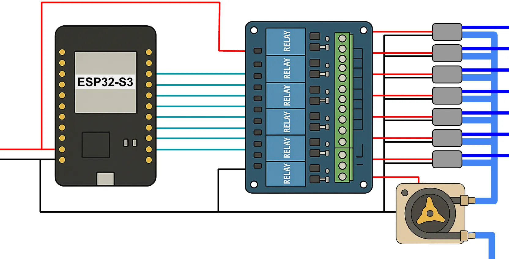
I picked an ESP32-S3 dev board as the brains of the controller, as I had never tried the newer ESP32 models, it’s convenient that they are USB-C, and I needed a ton of GPIO outputs so I think an ESP8266 would be too limiting. The ESP connects to a basic 8-channel relay board which in turn powers 7 solenoid valves and a pump, all rated at 5V to make it easier to run everything off the same power.
I figured I needed to wire it up like this:
Pump
There are lots of types of pump, and I bought three types to experiment with, all specific models that can operate at 5V:
- Centrifugal: these work by essentially ‘flinging’ water out of the side of a circular chamber with a paddle wheel. Really simple, often used for aquariums, quiet, and can also often be fully submerged. However they can’t muster very much pressure, and the flow rate will be highly suceptible to the difference in pressure between the inflow and outflow pipes.
- Peristaltic: often called ‘dosing’ pumps, these work by squeezing a flexible pipe and running a roller along it to push the liquid through the pipe in much the same way as you’d tease out the last bit of toothpaste from a tube. These can produce a bit more pressure at the same kind of voltage/price point, are still quite small, and their main advantage is that they can typically generate a quite consistent output flow that’s less sensitive to the pressure difference.
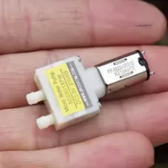
- Diaphragm: I picked up some seriously tiny M20 diaphragm pumps that work on the same principle as a bicycle tyre pump: two simple mechanical one-way valves, and a plunger that moves in and out. These were good at producing a consistent flow rate, both resisting upstream pressure and overcoming downstream backpressure, but have an annoying putt-putt-putt behaviour, and the flow rate was really tiny. I think they are designed mainly for use in robot vacuum cleaners to pump detergent.

To deliver 200ml of water, the centrifugal pump took around 8 seconds, but with even the slightest backpressure, it stopped working at all, and if a siphon started it would flow right through the pump with no hinderance at all. I feel like this just doesn’t offer enough control. The diaphrapm pump was so slow that 200ml took over 5 minutes. I’m sure I could probably find a faster one but I ended up picking the peristaltic pump - which gave me 200ml in around 1 minute, and was fairly consistent about it even with a 4 storey tall outflow pipe full of water trying to pull on the pump.
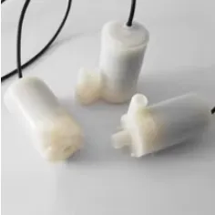
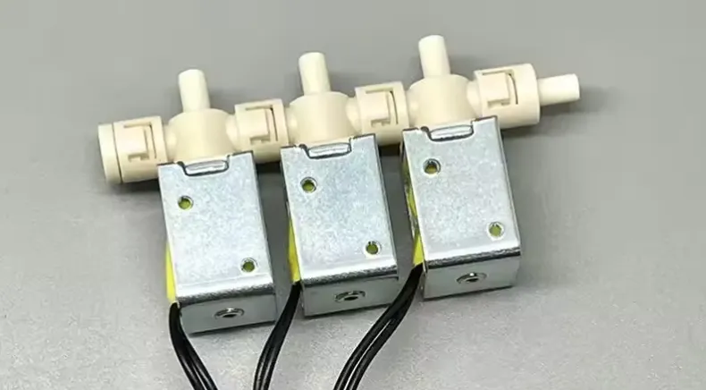
Valves
Like the pump, there are a lot of options for valves, but I ended up only buying one type, a normally-closed 5V solenoid valve. These open and close quickly, are very cheap, and in the event of a power loss, will close, so they fail safe.

If I needed to have the valve open for long periods I might consider a latching valve, which only requires power to open and close it, not to keep it in a given state, but the safety aspect of a normally-closed valve appealed to me most.
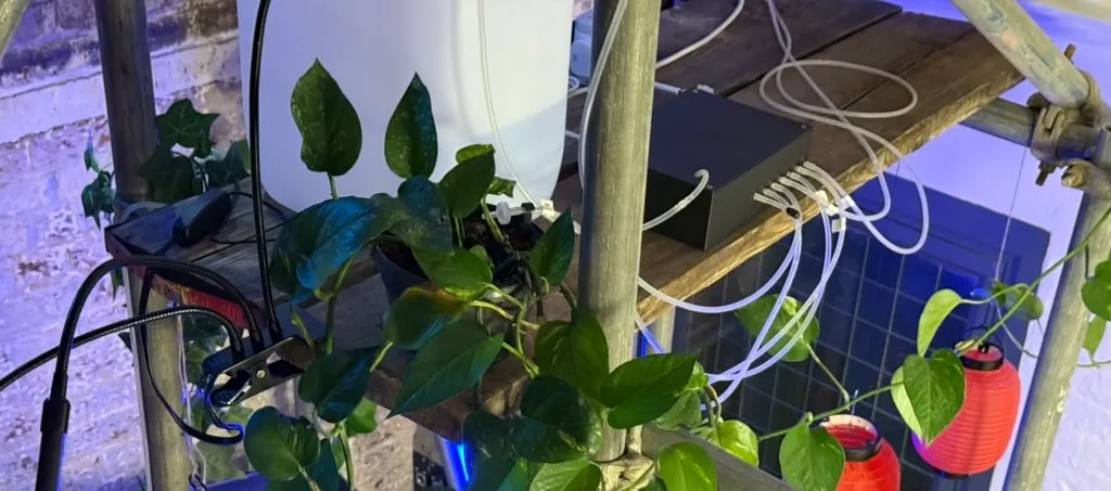
Plumbing
This part of the project is where I get very sore fingers pushing plastic pipes onto tiny connectors to feed from the pump into each solenoid valve and then out to a port on the outside of my 3D printed enclosure. Getting all the valves connected to the pump was the worst part, since they all sit very close to each other, so I split the output from the pump into two and made two levels of feeder pipe so I could fit enough T connectors in to reach every valve.
I later discovered you can get multi-way solenoid valves, including this one which is even chainable!
But this operates on 12V and I couldn’t find a 5V one. It would probably make sense to use these along with a 12V pump and a 12V power supply, and then step that voltage down for the microcontroller. But that would be a pretty big rebuild, and I’m not sure how safe it would be to step up the 5V supply to 12V to power an inductive load like a solenoid. So for now, my individual 5V valves work fine.
Handling inductive loads
Initially, I powered the system from an power extension cable that had a USB socket on the end as well as a bunch of mains sockets. The controller would boot, but as soon as I toggled a switch on the relay, it would reset.
A lot of googling and chatting to my engineer friend Dora Militaru and I realised that the problem was probably that there was too much voltage drop when the valves and the pump turned on - because these are inductive loads. That means they will draw a big current when they are first connected to power, then it will drop down quickly to their normal operating current. If the power supply can’t deliver that larger current, the voltage will drop and the microcontroller blacks out.
I switched from the probably very naff USB power supply in my random extension lead to a dedicated 5V, 2.5A power supply board, which I noted also includes a 1000uF capacitor across the output.
That’s good, it seems, because it means spikes in demand for current can exceed the supply’s capacity very briefly without causing instability in the voltage.
OK, now the pump and valves turn on successfully, but when they turn off, weird stuff happens: the microcontroller resets, or the switch bounces and the valve ends up still on. This turns out to be because of flyback - a reverse voltage spike that happens when the supply voltage is removed from a charged inductive load, causing the coil in the inductor to want to discharge in the opposite direction, rather like a spring bouncing back to its natural state when a weight is removed from it. That ‘flyback’ voltage can be significantly more than the supply voltage, and I guess I’m lucky it didn’t damage anything.
The solution to flyback is to add a rectifier diode across the inductor, which allows current to flow harmlessly around to the other side of the coil as it discharges, but will not conduct in the normal direction of the circuit.
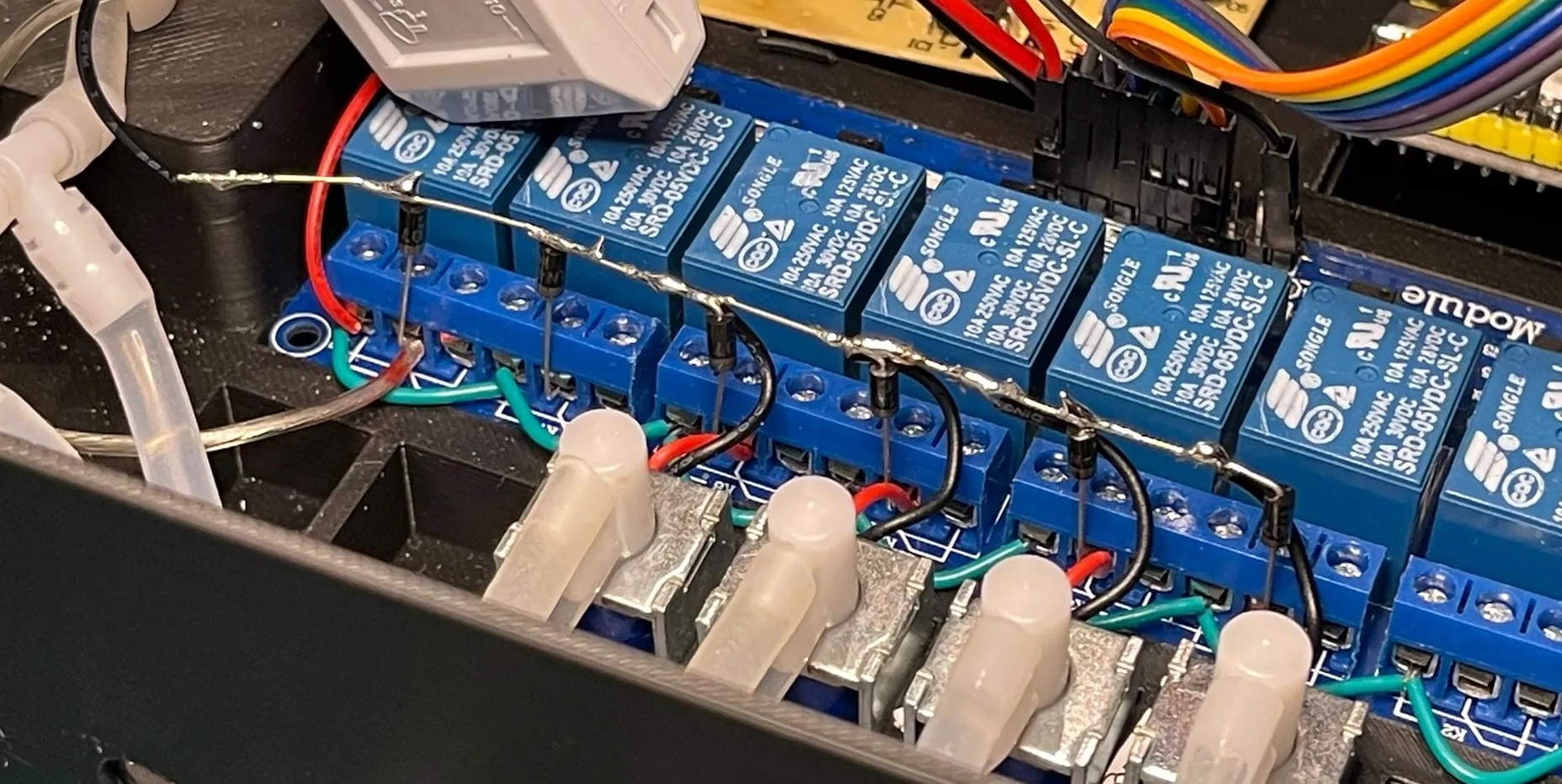
With my flyback diodes in place, the microcontroller no longer resets, and we’re in business!
Firmware with ESPHome
I started the firmware part of the project by creating an ESPHome configuration to specify the GPIOs that I was using for all the relays:
switch:
# Pump
- platform: gpio
pin: GPIO13
inverted: true
id: pump
name: "Pump"
# Output valves
- platform: gpio
pin: GPIO8
inverted: true
id: valve_1
name: "Valve 1"
- platform: gpio
pin: GPIO18
inverted: true
id: valve_2
name: "Valve 2"
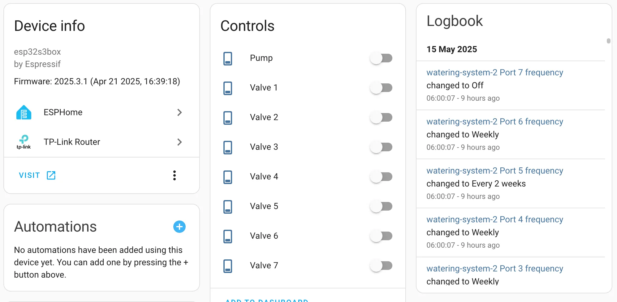
...In Home Assistant, I could now see switches for the pump and each of the valves, and toggle them on and off.
The rest is just automation. Done!
On-device automation
Hoooooooollldd on a minute. Switching the valves and pump from Home Assistant works, but it violates my Low chance of disaster requirement. What if HA turns the pump on and then crashes? Or the wifi goes out? Then HA can’t turn the pump off and my plant gets very wet and then my house gets very wet. We need to handle the duration of each watering action on the microcontroller itself without any reliance on an external signal to turn it off. So let’s also create a “number” entity to store the flow rate in ml per minute, and one for each port to store the volume we want for each plant:
number:
  - id: ml_per_minute
    name: "Flow rate"
    platform: template
    min_value: 1
    max_value: 10000
    initial_value: 227
    step: 1
    unit_of_measurement: ml/min
    update_interval: never
    optimistic: true
    restore_value: true
    mode: box
    entity_category: config
  - id: port_1_ml
    name: "Port 1 volume"
    platform: template
    min_value: 0
    max_value: 500
    initial_value: 20
    step: 1
    unit_of_measurement: ml
    update_interval: never
    optimistic: true
    restore_value: true
    mode: box
    icon: "mdi:watering-can"
    entity_category: config
  ...
Now we can add a ‘button’ entity that runs a set of actions to turn the pump on and each of the valves on and off in turn:
script:
  - id: do_watering
    mode: queued
    parameters:
      port_number: int
    then:
      - lambda: |-
          float flow_rate = id(ml_per_minute).state;
          ESP_LOGI("watering_system", "Delivering %d ml to pump %d (%d ms, %f)", water_volume_ml, pump_id, time_milliseconds, flow_rate);
          id(pump).turn_on();
          if (id(port_1_ml).state > 0) {
            id(valve_1).turn_on();
            int time_1 = (id(port_1_ml).state / flow_rate) * 60.0 * 1000;
            delay(time_1);
            id(valve_1).turn_off();
          } else if (id(port_2_ml).state > 0) {
            id(valve_2).turn_on();
            int time_2 = (id(port_2_ml).state / flow_rate) * 60.0 * 1000;
            delay(time_2);
            id(valve_2).turn_off();
          } else if( ... ) {
            ...
          }
In Home Assistant, it’s then just a case of automating the pressing of the button.
On-device scheduling
OK but now the problem is that all the plants get watered in one action. One of my requirements was that Every plant gets different amounts of water, on different intervals. We have got the “different amounts of water” but we can no longer water only specific plants. I could add a button per plant. But how about reducing the dependency on HA even further and put the scheduling on the microcontroller as well?
For this, we need two new entities per port: a select to determine the watering frequency, and a datetime to record when we expect the next watering to happen. Here’s how I specified those (and repeated it for every port):
select:
  - id: port_1_freq
    name: "Port 1 frequency"
    platform: template
    options:
     - "Off"
     - "Daily"
     - "Twice a week"
     - "Weekly"
     - "Every 2 weeks"
     - "Monthly"
    update_interval: never
    initial_option: "Off"
    optimistic: true
    restore_value: true
    icon: "mdi:calendar-clock"
    entity_category: config

datetime:
  - id: port_1_next
    name: Port 1 next due
    platform: template
    type: datetime
    optimistic: yes
    initial_value: "2020-01-01 12:00:00"
    restore_value: true
    icon: "mdi:calendar"
    entity_category: config
    on_time:
      then:
        - logger.log: "Activating port 1!"
        - script.execute:
            id: do_watering
            port_number: 1
Conveniently, datetime entities have an on_time automation hook that will run an action at the moment indicated by the time stored in the entity, so we can use this to trigger the watering. That means moving the button actions to a ‘script’, and since I now need to do date and time maths, I figured the script may as well now be pure lambda:
script:
  - id: do_watering
    mode: queued
    parameters:
      port_number: int
    then:
      - lambda: |-

          // Repeat first element to align array indicies with ID number of port
          auto next_dates = std::array<esphome::template_::TemplateDateTime*, 8> {
            id(port_1_next), id(port_1_next), id(port_2_next), id(port_3_next), id(port_4_next), id(port_5_next), id(port_6_next), id(port_7_next)
          };
          auto port_vols = std::array<esphome::template_::TemplateNumber*, 8> {
            id(port_1_ml), id(port_1_ml), id(port_2_ml), id(port_3_ml), id(port_4_ml), id(port_5_ml), id(port_6_ml), id(port_7_ml)
          };
          auto port_valves = std::array<esphome::gpio::GPIOSwitch*, 8> {
            id(valve_1), id(valve_1), id(valve_2), id(valve_3), id(valve_4), id(valve_5), id(valve_6), id(valve_7)
          };

          int watering_volume_ml = port_vols[port_number]->state + 0;
          long now = id(homeassistant_time).now().timestamp;

          if (id(pump_on_timestamp) > 0) {
            ESP_LOGW("script", "Pump already running");
          } else if (watering_volume_ml == 0) {
            ESP_LOGD("script", "Port %d volume set to zero", port_number);
          } else if (next_dates[port_number]->state_as_esptime().timestamp > now) {
            ESP_LOGD("script", "Port %d watering not yet due", port_number);
          } else {

            id(pump_on_timestamp) = id(homeassistant_time).now().timestamp;
            id(current_watering_duration_ms) = (port_vols[port_number]->state / id(ml_per_minute).state) * 60.0 * 1000;

            float duration_seconds = id(current_watering_duration_ms) / 1000;

            ESP_LOGI("script", "Start watering port %d: %dml %.0fs", port_number, watering_volume_ml, duration_seconds);
            port_valves[port_number]->turn_on();
            id(pump).turn_on();
          }
      - if:
          condition:
            lambda: "return id(pump_on_timestamp) > 0;"
          then:
            - delay: !lambda "return id(current_watering_duration_ms);" # Async, better than doing in lambda
            - lambda: |-

                auto next_dates = std::array<esphome::template_::TemplateDateTime*, 8> {
                  id(port_1_next), id(port_1_next), id(port_2_next), id(port_3_next), id(port_4_next), id(port_5_next), id(port_6_next), id(port_7_next)
                };
                auto freqs = std::array<esphome::template_::TemplateSelect*, 8> {
                  id(port_1_freq), id(port_1_freq), id(port_2_freq), id(port_3_freq), id(port_4_freq), id(port_5_freq), id(port_6_freq), id(port_7_freq)
                };
                auto port_valves = std::array<esphome::gpio::GPIOSwitch*, 8> {
                  id(valve_1), id(valve_1), id(valve_2), id(valve_3), id(valve_4), id(valve_5), id(valve_6), id(valve_7)
                };

                ESP_LOGD("script", "Finished watering port %d", port_number);

                id(pump).turn_off();
                port_valves[port_number]->turn_off();

                time_t t = next_dates[port_number]->state_as_esptime().timestamp;
                int days_to_add = 0;

                if (freqs[port_number]->state == "Daily") {
                  days_to_add = 1;
                } else if (freqs[port_number]->state == "Twice a week") {
                  days_to_add = 3;
                } else if (freqs[port_number]->state == "Weekly") {
                  days_to_add = 7;
                } else if (freqs[port_number]->state == "Every 2 weeks") {
                  days_to_add = 14;
                } else if (freqs[port_number]->state == "Monthly") {
                  days_to_add = 30;
                } else {
                  ESP_LOGD("script", "Port %d frequency is Off or unknown: %s", port_number, freqs[port_number]->state.c_str());
                }

                if (days_to_add > 0) {
                  t += (86400 * days_to_add);
                  ESP_LOGD("script", "(3) %d", t);
                  auto call = next_dates[port_number]->make_call();
                  call.set_datetime(t);
                  call.perform();
                  ESP_LOGD("script", "Scheduled port %d for next watering at %d", port_number, t);
                }

                id(pump_on_timestamp) = 0;
                id(current_watering_duration_ms) = 0;
This code is almost certainly garbage because my C++ knowledge is very much at the “ChatGPT told me to” level, but it seems to work.
To make this work, I also needed my microcontroller to know the current time. This is easily done with a time entity, and getting the time from Home Assistant is the recommended way to source it:
time:
  - platform: homeassistant
    id: homeassistant_time
    timezone: Europe/London
And I figured it would be good to avoid trying to run a watering action if there was one already running, so the code also keeps track of that state using id(pump_on_timestamp) and id(current_watering_duration_ms), which reference some globals I defined:
globals:
  - id: pump_on_timestamp
    type: int
    restore_value: false
    initial_value: '0'
  - id: current_watering_duration_ms
    type: int
    restore_value: false
    initial_value: '0'
The frequencies and timestamps are exposed in Home Assistant, which is quite a lot of entities, so I figured I could now make a nice dashboard to group them by plant:
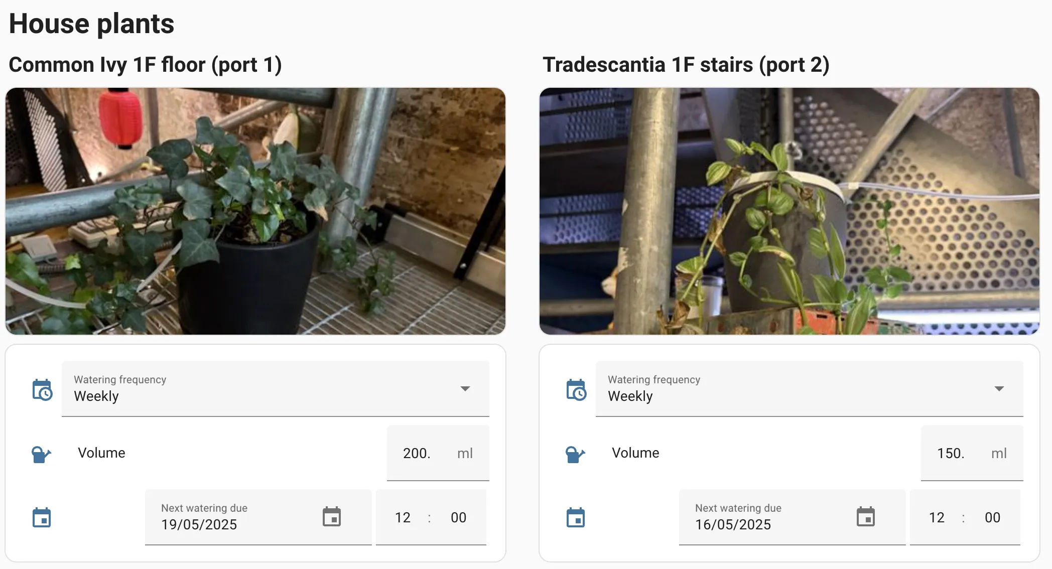
Consolidating repetitive config with packages
My ESPHome config was now really long, and I was looking for a way to reduce the amount of repetition. I searched for “templates” and didn’t find anything, but I was later looking at a different project, esphome-modular-lvgl-buttons and noticed that they were doing what I needed to reduce repetition in my watering project - and the magic word is packages.
Packages allow me to define a set of configuration for a generic “port”, and then create each one with much less detail. Let’s start by bringing all the ‘port’ related config into one file, and replace all the instances of the port number with the variables ${id} and ${pin}. I now have four entities per port:
- Water volume:
number, e.g.port_1_ml. Number of millilters to deliver to the port each time the plant is watered. - Frequency:
select, e.g.port_1_freq. How often to water - options like “Weekly”. - Next watering:
datetime, e.g.port_1_next. When to next water the plant. - Valve:
switch, eg.valve_1. The handle for the GPIO that controls the solenoid valve for this port.
All this can now be abstractly defined in a port.yaml file alongside my main esphome file, like this:
number:
  - id: port_${id}_ml
    name: "Port ${id} volume"
    platform: template
    min_value: 0
    max_value: 500
    initial_value: 20
    step: 1
    unit_of_measurement: ml
    update_interval: never
    optimistic: true
    restore_value: true
    mode: box
    icon: "mdi:watering-can"
    entity_category: config

select:
  - id: port_${id}_freq
    name: "Port ${id} frequency"
    platform: template
    options:
     - "Off"
     - "Daily"
     - "Twice a week"
     - "Weekly"
     - "Every 2 weeks"
     - "Monthly"
    update_interval: never
    initial_option: "Off"
    optimistic: true
    restore_value: true
    icon: "mdi:calendar-clock"
    entity_category: config

datetime:
  - id: port_${id}_next
    name: Port ${id} next due
    platform: template
    type: datetime
    optimistic: yes
    initial_value: "2020-01-01 12:00:00"
    restore_value: true
    icon: "mdi:calendar"
    entity_category: config
    on_time:
      then:
        - logger.log: "Activating port ${id}!"
        - script.execute:
            id: do_watering
            port_number: ${id}

switch:
  # Output valves
  - platform: gpio
    pin: ${pin}
    inverted: true
    id: valve_${id}
    name: "Valve ${id}"
Now, in my main esphome config, I can do this:
packages:
  port_1: !include
    file: port.yaml
    vars:
      id: 1
      pin: GPIO8
  port_1: !include
    file: port.yaml
    vars:
      id: 2
      pin: GPIO18
...
This reduces the overall amount of code by about 300 lines. Nice!
Learnings and next steps
OK, what have we all learned here today?
- If you have inductive loads, you need a bulk decoupling capacitor and most importantly, flyback diodes.
- Packages help to make ESPHome configs much less repetitive
- Using arrays in ESPHome lambdas allows for dynamically addressing entities like switches and numbers
- The
datetimetype is kinda funky and especially the way it interacts with types in lambdas, but I found the most reliable method was to convert it to alongand just treat it as a unix timestamp. I’m hoping it will be OK with DST changes. - Plants will die anyway. Stupid plants.
Things I’d change if I did it again:
- Using a multi-way solenoid valve would be much easier to plumb.
- The switching relays I used are the most common type for hobby projects and are loud and really large. I subsequently found an 8-way solid state relay board that is a third of the size and silent in operation, I’d probably swap that out if I could be bothered to reprint the enclosure.
- Using 12V would probably give me access to a bigger range of solenoid options and more reliable operation (since we do need to overcome the force of a magnet and the pressure of the water, and 5V is pretty naff for anything requiring physical force). A simple buck converter would be all I’d need to step 12V down to 5V for the microcontroller.
The next step is to accomodate more plants. I could make another unit without a pump, and use it to switch one of the outputs from the first controller to multiple plants, avoiding the need for a ton of piping. Or I could rework the existing controller to have more outputs, and use the multi-way solenoid and solid state relays to reduce the overall size. A single ESP32 has more than 30 GPIOs so in theory I could get a lot out of one controller.